|
Technical Issues - FilmStar News 2022
Other editions:
2006, 2007, 2008,
2009, 2010,
2011, 2012
2013,
2014,
2015,
2016,
2017, 2018,
2019,
2020,
2021, 2023, 2024, 2025
January 24...Displaying Monitor Spectra
in the Interactor
Revised January 26
A user recently requested the ability to compare theoretical and
measured optical monitor curves (%R/%T vs. layer thickness) in the Interactor.
While seemingly unavailable, the
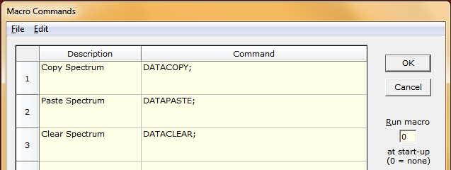
capability is implemented through 'DATA' macro commands. DESIGN 2.61.4690
makes the procedure somewhat more convenient.

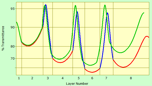
As the Interactor screen capture shows,
BLUE indicates
calculated H layers, RED
calculated L layers, and
GREEN monitor trace (simulated here by Copy/Paste
Spectrum). As the design is modified, the green trace moves
(confusingly?) as the horizontal scale follows layer thicknesses
changes. In addition there is the issue of physical thickness
accuracy in the deposited film. We await reports as to the
method's effectiveness.
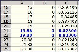
Care is
required to ensure that the optical monitor trace
has the DESIGN data format. Column A is total thickness
(nm), Column B is reflectance (0-1) and Column C is
transmittance (0-1).
Note that the end of Layer 1 and beginning of Layer 2
have the same values because the monitor wavelengths
for the adjacent layers are the same. Deleting Row
21 or Row 22 gives the same monitor trace in DESIGN.
(Unequal wavelengths give vertical jumps at boundaries.
Check Specify evaluation wavelengths... in the
Graph Axes dialog.)
Users needing help with Macro Commands or requiring
additional
explanation should
contact FTG Software.
|
 |
February 18...MEASURE Scan Methods
with the FilmStar Database
Recently
a user expressed interest in utilizing the
FilmStar Database for MEASURE
Scan Methods.
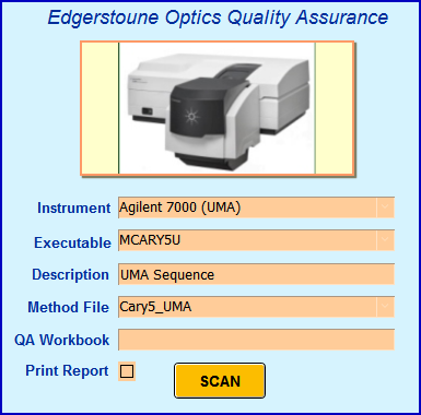
Typically, FilmStar BASIC exports FileMaker script commands
(F*S >> FM). Another possibility is a FileMaker front end (FM >>
F*S). You might, for example, include photos showing
system setup as well as instructions in local
languages.
How does it work? FileMaker's Send DDE Execute
command triggers FilmStar Macro Commands, for example
sending SCANPLOT to MPE983|Main to scan
and plot the spectrum. Ultimately, BASRUN or
BASEXEC returns macro commands for saving spectra in a separate database.
DDE commands can also be sent to Excel for pass/fail
analysis. While there are a large number of MEASURE DDE
macro commands, more can be added as required.
Contact FTG for an
online
explanation or see for yourself how the
SCAN
button works:
Scan Methods:
Methods.zip (Test Mode)
Unzip to C:\Winfilm\Measure (or ..Scantraq)
FileMaker Database:
Methods.fmp12
FileMaker 45 Day
FREE TRIAL Win 10/11
|
Cary UMA: Mcary5U 2.51.2062 required |
March 11...Tooling Factor global search
Minor Revision August 1
A user reported that Tooling Factor
determination failed. As did not provide details enabling us to
reproduce the issue, we assumed that initial default tooling factors (1.0) were too far from the solution,
therefore giving a local minimum with Cannot invert singular
matrix error.
Gedankenspektrum analysis: Using design
ToolTest.faw we simulated a
'Measured' spectrum by assigning (random) values L:1.138
& H:1.356
in Setup...Tooling Factors. The spectrum was converted to
optimization targets. We next reset default
initial factors L:1.0 and H:1.0
and solved for tooling factors via the dialog's <Compute> button. The solution is given in the
DLS column. (Tooling
factor determination always uses DLS).
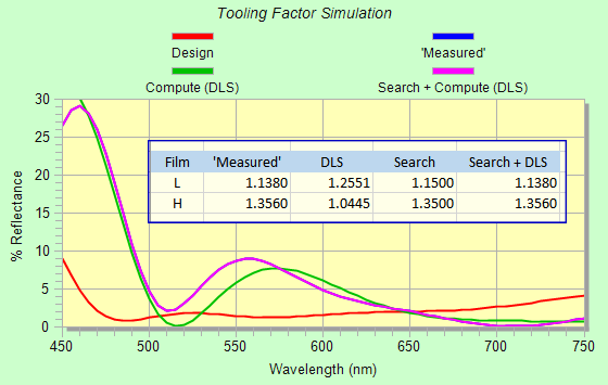
Noting that DLS
Tooling Factors 1.2551 and 1.0445 are erroneous local minima, we
implement
Plan B: a simple BASIC code searching for closest initial factors.
' ToolSearch.bas for
FilmStar DESIGN
' Tooling Factor
global search
' Two
film materials: L (Film 1, Row 3) in Film Indices and H (Film
2, Row 4)
DefDbl A-Z
Sub Main
vBest = 10^8
Tooling$ = "1 1"
' Default starting values
AxesDraw
Calculate
Replot
For fL = 1 To 1.5 Step 0.05
' Modify ranges as
required
For fH = 1 To 1.5 Step 0.05
Tooling$ =
CStr(fL) & " " & CStr(fH)
v = Merit
' FilmStar BASIC
function Merit
If v < vBest
Then vBest = v: fLbest = fL: fHbest = fH
Next fH
Next fL
Tooling$ = CStr(fLbest) & " " & CStr(fHbest)
' New starting
values
AxesDraw
Calculate
Replot
End Sub
New factors are displayed above in the Search column.
We now return to Setup...Tooling Factors and once
again click <Compute>. Results in the
Search + DLS column now match the
'Measured' column.
Users requiring help implementing BASIC code should contact FTG
Software.
March 28...CIE + %T targets Design
Exercise
A user asked about a design with
T=10% CIE response (D65 illumination) and maximum %T from 870 to 890
nm. Starting with a standard highpass stack we set up a
Workbook with
Objective
F6+G6+0.02*H6+(1-AVERAGE(D499:D519))
and Workbook Macro
CALCULATE;BasExec Dim
x!, y!, yy!|GetCie x, y, yy|WbSetNum "B6", x|WbSetNum "C6",
y|WbSetNum "D6", yy;.
BasExec inserts BASIC code directly
into the Workbook. Sub Main and End Sub are added
automatically and "|" is equivalent to CRLF. BasExec is not intended for code containing multiple
subroutines. More about BasExec:
here &
here. |
Sub Main
Dim x!, y!, yy!
GetCie x, y, yy
WbSetNum "B6", x
WbSetNum "C6", y
WbSetNum "D6", yy
End Sub |
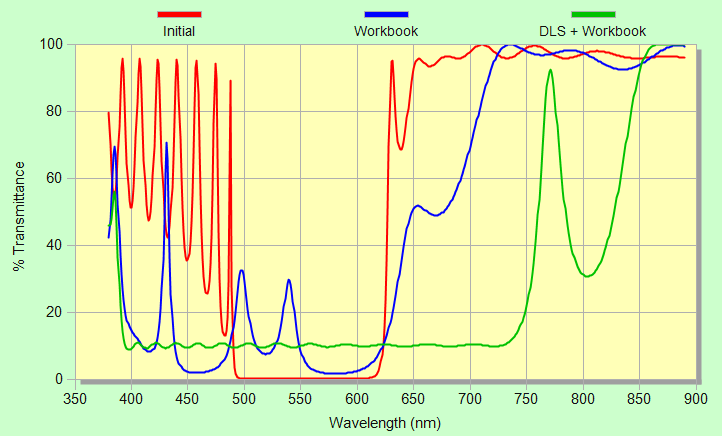
CIE targets are X=.3127, Y = .3290, YY=
10. While there is a great difference between the
blue (Workbook only) and
green (DLS+Workbook)
spectra, that difference might not be apparent when viewed at 0°, as
indicated by the coordinates given below. Ripple in the Workbook
solution can be reduced by constraining the standard deviation (STDEV).
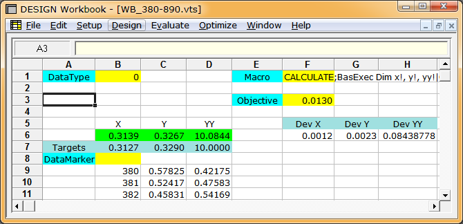
Workbook Optimization
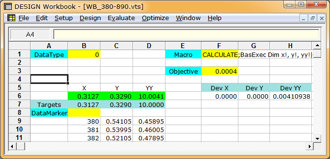
DLS + Workbook Optimization
Will two radically different designs
look the same?

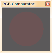
Referring to the four
Comparator images above, we see no color difference
between the designs at normal incidence. The Workbook
design, however, shifts to red at 30° while the DLS
design remains neutral.
In the image at the right, the rectangle corresponds to
WB 0° while the circle corresponds to WB 15°. We expect
that an observer would have little difficulty in
distinguishing the two designs.
Considering only normal incidence, is the DLS design
more stable than the
Workbook design? As shown below, the DLS
CIE scatter plot (S.D. = 2%) is essentially the same as Workbook only. |
 |
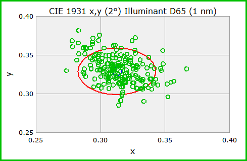
DLS + Workbook 75% Yield
%2074.png)
Workbook 74% Yield
Optimization Targets in a Workbook
Objective: Transferring 380 to 890 x 1 nm spectra is
wasteful if we only utilize 870-890 nm in the Objective. We
speed-up calculations with Optimization Targets 870 to 890 x 1 nm
and Workbook Macro
BasExec Dim x!, y!,
yy!|WbSetNum "G3", Merit|GetCie x, y, yy|WbSetNum "B6",
x|WbSetNum "C6", y|WbSetNum "D6", yy;
and Objective Function
F6+G6+0.02*H6+0.2*G3.
The Workbook (tutorial) is a complex
component enabling optimization scenarios not otherwise possible;
users requiring further explanation or assistance should contact FTG
Software to arrange a
ZOOM meeting.
June 14...Target Generator Update
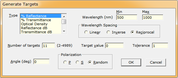
Updated Target Generator adds Reciprocal Wavelength
Spacing
Inverse spacing works as follows: a 2 nm interval at
500 nm becomes a 4 nm interval at 1000 nm and an 8 nm
interval at 2000 nm. This was originally added to speed
calculations and has been in DESIGN for many years.
Inverse spacing, however, adds relatively too many IR
targets and too few UV targets for very wide band
coatings.
The new Reciprocal Wavelength Spacing option gives
equal frequency intervals for wavelengths in nm. This
better obeys the 11th Commandment "Thou shalt
have more targets than wiggles." (Note: Columns A-C
computed by DESIGN, Column D computed with Excel formula
D2=10^7/C2, etc.)
This simplifies target spacing. Previously, a designer
requiring frequency-spaced wavelengths would need to
create targets in 1/cm and then convert to nm or µm. |
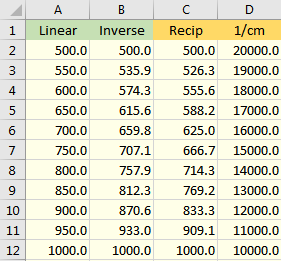 |
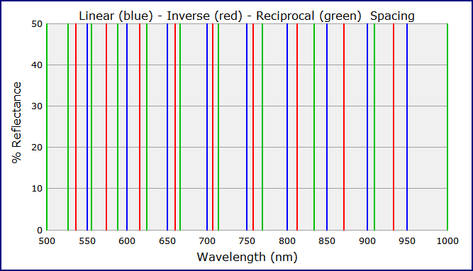
Note: Lines overlap at 500 and 1000 nm
July 6..Wavelength List Generator Update
The Wavelength List Generator (Setup...Wavelength
List...File..Generate) has been updated in DESIGN 2.61.4731
and MEASURE 2.51.2080 with spacing options similar to the Target Generator (above).
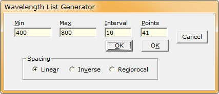
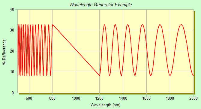
Inverse and Reciprocal
(shown below) spacing are especially useful for speeding up
Workbook optimization. If
reflectance between 800 and 1200 nm is unspecified it can be
ignored. Note that <Ctrl+D> deletes a single cell or range of
highlighted cells in the Wavelength List dialog.
August 12..Lorentzian Dispersion
Functions Revisited
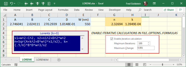
Lorentzian functions are very useful in characterizing
dielectric materials. Built-in User Index functions LOREN and LORENK have
now been supplemented with LORENM and LORENKM (DESIGN 2.61.4743,
INDEX 2.51.0688) wherein coefficients C and D (LORENKM) are µm-based.

DESIGN/INDEX n,k calculations can
be verified in Excel.
Click here
to download. The FilmStar BASIC code below can be used to check DESIGN
calculations. Don't forget to add LORENK etc. to the list of
available built-in functions. Otherwise it will not appear in
the pull-down Dispersion list.
Sub Main
GetIndex "Z", 550, xn!, xk!
Debug.Print xn
Debug.Print xk
End Sub
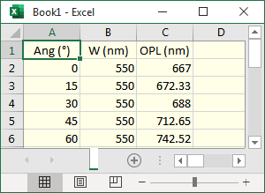
August 29...Optical Path Length
A user needs to compute
optical path length (OPL) in a film stack.
OPL is the sum of n*d where n is index and d is path
length, typically in nm. We thought it best to implement
as an instructive
BASIC macro (shown below) thereby giving users
output format flexibility.
Click here to download the design illustrated
here.
Noting that path length increase with angle (Snell's law)...
tPath = n2/Cos(Arcsin(Sin(Angle)*n1/n2))
or lacking an Arcsin function
tPath = n2/Sqr(1-(Sin(Angle)*n1/n2)^2)
where n1 is entrance medium
index (usually 1) and n2 film index. |
 |
In the code below there are two
Sub Main versions. Comment-out the version not being used.
' OpticalPathLength.bas for FilmStar DESIGN
' Copyright 2022 FTG Software Associates
' Computes total path length Σ n*d
Option Base 1
DefInt I-N
DefSng A-H, O-Z
Option Explicit
Const aRad = 57.2957795 ' Converts angle to radians
'Sub Main ' simple single wavelength case uses current calculation angle
' Calculate ' Recommended (loads n,k
tables)
' Debug.Print Format$(tOptical(550),
"0.00") & " nm"
'End Sub
Sub Main 'Print in Immediate window & copy to Clipboard
Dim Ang, Wave, Clip$
Clip$ = "Ang (°)" & vbTab & "W (nm)" & vbTab & "OPL (nm)" & vbCrLf
' Header row
Calculate
' Recommended (loads
n,k tables)
For Wave = 400 To 800 Step 50 ' Set same min and max if no dispersion
For Ang = 0 To 75 Step 15
Angle = Ang ' Set calculation angle
Debug.Print "Ang " & CStr(Ang) & "°, W (nm) " & CStr(Wave) & _
" nm: OPL=" & Format$(tOptical(Wave), 2) & " nm"
Clip$ = Clip$ & CStr(Ang) & vbTab & CStr(Wave) & vbTab & _
Format$(tOptical(Wave), "0.00") & vbCrLf
Next Ang
Next Wave
Clipboard Clip$ ' Paste into Excel
End Sub
Function tOptical(ByVal Wave)
Dim symb$(), nTyp$(), nFile$(), nDesc$(), tSymb$
Dim i, k, tPath(), t, qd(), qt$(), qdesc$(), nMatl, xn, xn1, xk, nLay
DesignConvert 1, "N" ' Physical thickness in nm
GetIndexList symb$(), nTyp$(), nFile$(), nDesc$()
nMatl = UBound(symb$)
For i = 3 To nMatl
tSymb$ = tSymb$ & symb$(i)
Next i
ReDim tPath(3 To nMatl)
' If ".itw" error in
GetIndex, Calculate spectrum and try again
GetIndex 1, Wave, xn1, xk ' xn1 is entrance medium index
For i = 3 To nMatl
GetIndex i, Wave, xn, xk
tPath(i) = xn/Sqr(1-(Sin(Angle/aRad)*xn1/xn)^2) '
d 1/cos increase
Next i
GetLayers nLay, qd(), qt(), qdesc()
' Converts Groups;
Stack Mode not supported
For i = 1 To nLay
k = InStr(tSymb$, qt(i)) + 2
t = t + qd(i) * tPath(k)
Next i
tOptical = t
End Function
If you've read this far you
might be interested in improving FilmStar BASIC skills. Please
contact FTG Software with any issues.
|
Exercise 1
Intermediate |
Using FilmStar
BASIC XL--- functions, code a Sub Main which
directly saves in Excel XLS or XLSX. |
|
Exercise 2
Advanced |
Implement
OPL as a constraint in Workbook optimization. Start with
FilmStar BASIC Wb--- functions to set required cell
values. |
September 2...Verifying THK
Variable(s) in DESIGN
DESIGN
2.61.4744 (Sep 1) erroneously disabled
BASIC Sub IndexGet
in Stack Mode.
Fixed in 2.61.4745.
Users need to verify dispersion functions
in DESIGN. While verifying (n,k) vs. wavelength and vs. thickness is
(slowly) possible in the
Index Formulator, n,k arrays can be plotted in Excel or
INDEX.
THK variables in User-Defined Index Functions are the basis of
Double Dispersion.
Users should verify calculations with a
DESIGN BASIC macro based on the listings below. Since
layers of the same material can have different refractive
indices, Stack
Mode is required when THK variables are specified.
Option Explicit
' Optional but
always a good idea
DefSng A-H, O-Z
Sub Main ' Versus
layer thickness (THK variables)
Dim t, s$, xn, xk
s$ = "t (nm)" & vbTab & "n" & vbTab & "k" & vbCrLf
' Row header
Calculate '
Loads dispersion
For t = 0 To 200 Step 20
SetLayerThk 2, t
' Layer 2 is in Row
4
GetIndex 4, 550, xn, xk
' 550 nm
' Debug.Print CStr(t)
& ": " & CStr(xn) & ", " & CStr(xk)
s$ = s$ &
CStr(t) &vbTab & CStr(xn) & vbTab & CStr(xk) & vbCrLf
Next t
Clipboard s$ ' Paste
into Excel
End Sub
Calculate loads n,k
tables. Alternatively, click Evaluate...Recalculate <F9> before running the macro the first
time. Repeat if you modify index tables. Hint: Calculating before running the macro
reveals any errors. When learning about THK variables, start
with a very simple function such as
-(THK<=100)*1.5-(THK>100)*2.5
wherein n is 1.5 when t<=100 nm and 2.5 otherwise.
With no THK variables, calculations are
simplified and GetIndex refers to either the Film Indices row
number OR Stack Mode editor row number. Here we evaluate as a function of wavelength
and eliminate the header line:
Option Explicit
DefSng A-H, O-Z
Sub Main '
Versus wavelength
Dim s$, xn, xk, wave
Calculate '
Loads dispersion
For wave = 400 To 800 Step 20
GetIndex 4, wave, xn, xk
' Row 4 in either
Film Indices or Stack editor
' Debug.Print
CStr(wave) & ": " & CStr(xn) & ", " & CStr(xk)
s$ = s$ & CStr(wave) & vbTab &
CStr(xn) & vbTab & CStr(xk) & vbCrLf
Next wave
Clipboard s$ ' Paste
into INDEX (or Excel)
End Sub
Please contact FTG Software
with issues and comments. No BASIC experience? Review our
BASIC Tutorials and contact us
for a ZOOM meeing.
September 9...MEASURE BASIC FileSave
Bug
A user asked about adding a
description line to CSV spectra. In testing BASIC Property
FileDescription, we found that BASIC Function FileSave failed.
The bug, fixed in 2.51.2084, is in revisions updated earlier
this year.
How to test FileSave:
Sub Main
Scan ' Use Test Mode
or open/paste spectrum
FileDescription(1) = "Test A (FileSave)"
FileSave "C:\Winfilm\Spectra\TestA.csv"
End Sub
If FileSave is defective
TestA.csv is not created. In that case,
update if
possible or use the equivalent alternative BASIC code listed
here:
Sub Main ' Plan B
Scan ' Use Test Mode
or open/paste spectrum
FileDescription(1) = "Test B (DATASAVE)"
Macro "DATASAVE C:\Winfilm\Spectra\TestB.csv"
End Sub
September 19...Font Size Multiplier
(DESIGN Interactor & INDEX)
FilmStar has numerous graphics
options for publications, PowerPoints web pages, etc.
A user, planning to utilize DESIGN Interactor plots and INDEX n,k
plots in publications, found font sizes to be too small.
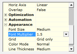
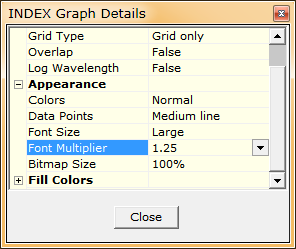
The
Font Multiplier setting in File..Configuration..Misc applied to
both Interactor and INDEX plots. Reviewing this
capability, we recognized the need for separate multipliers, as
introduced in DESIGN 2.61.4748/INDEX 2.51.0691. Font Multiplier
settings have been relocated as shown
below.
|
DESIGN Interactor Appearance |
INDEX
Graph Details <Ctrl+H> |
The
following applies mainly to the DESIGN Interactor: With
very large fonts, vertical axes labels may be displayed with
a smaller font as FSPlot automatically prevents overlap. One
fix is to increase window height. Another fix is to
shorten labels, for example, replace '% Reflectance' by
'% Refl' in File..Configuration..Misc. This facility,
intended originally for non-English languages, gets a new
purpose. Font Multiplier settings do not affect FSPlot
fonts.
October 28...Copying INDEX n,k Tables
to Excel
Index tables saved in separate
sheets
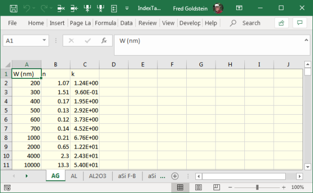
A user
requested means to copy numerous INDEX tables to
Excel in order to compare multiple files and determine
which are redundant or too low resolution as in AG above.
Instructive (VBA code not hidden) multi-sheet examples:
IndexTablesEarly.xlsm (early binding)
IndexTablesLate.xlsm (late binding)
Note the format options in
Sub FileToSheet.
Header rows (not shown above) require INDEX 2.51.0692
(Nov 1) with updated BASIC Sub IndexCopy.
Early binding
is useful when writing code as
IntelliSense is supported. Late binding lacks
Intellisense but is less fussy regarding its connection
with, in this case, FilmStar INDEX.
Sheets are loaded in alphanumeric order. Should you
manually add sheets later,
reorder with this VBA code. Try
this version to save all data in one worksheet.
Users requiring help should contact FTG Software. Those
learning VBA will find books and courses by searching
"learn Excel VBA".
|
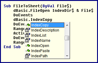
VBA IntelliSense pull-down for INDEX object |
November 4...Modifying Plot Module
Legends
A user
requested options in Collector-generated Plot Module
graphics.
DESIGN 2.61.4758 and MEASURE (Scantraq) 2.51.2092 extend
BASIC Property PlotLegend with the ability to
read [t$=PlotLegend(i)]
as well as assign [PlotLegend(i)=t$] labels.
This modification plus new BASIC Sub PlotRedraw allows
legends to be automatically modified.
This capability should also be useful when dealing with
Photon RT formats.
Hint: If there are both %R and %T columns in the
Collector, set the y-axis label to '% Response' by
setting Auto Y-Axis Label to False in the Main
Menu Graph Details dialog (<Ctrl+H>). |
Sub Main
Dim i%
For i = 1 To 12
s$ = PlotLegend(i)
If s$ <> "" Then
s$ =
Replace(s$, "RP", "%R P-pol")
s$ =
Replace(s$, "RS", "%R S-pol")
s$ =
Replace(s$, "RR", "%R R-pol")
s$ =
Replace(s$, "TP", "%T P-pol")
s$ =
Replace(s$, "TS", "%T S-pol")
s$ =
Replace(s$, "TR", "%T R-pol")
PlotLegend(i)
= " " & s$ & "°"
End If
Next i
PlotRedraw
End Sub |

Legends created by the Collector
module

Legends modified by the BASIC code
listed above
November 29...DESIGN Tolerancing
Algorithm
A user had questiones
about DESIGN's tolerancing function and its mathematics.
We thought the best way to show how it works is in an
Excel workbook.
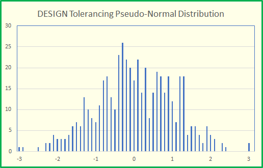
Pseudo-random numbers are multiplied by either
Abs Error or % Error limited to ±Max Error.
Basing selling price on tolerancing is better than
guessing, but not as useful as
pricing based on previous
production.
Yield estimation for complex requirements is possible in
the DESIGN Workbook
|
 |
December 12...Importing OLIS 983
Spectra
The
OLIS 983 modernizes the venerable PE 983 IR grating
spectrophotometer. While FilmStar MEASURE does not directly
control the OLIS 983, the Scan button (or a Macro button) can be
set to import
spectra from OLIS Excel files. In this case the 'instrument' is
actually the Mpe983 Raw Data Server in the Scan Method dialog.
MEASURE Mpe983.exe version 2.51.2094 adds optional BASIC FileOpen parameters enabling users to open OLIS and other Excel
files wherein column 1 is wavelength and additional columns are
response. FileOpen also allows for multiple header lines
(default 1). When triggered by the Scan button via attached Scan
Macro, reflectance is normalized (reduced) according to the
specified Standard file. Alternatively, a separate BASIC macro
containing DataReduce is possible.
|
The Scan
Macro is given by the BASIC code shown at the top right,
specified in Scan Method 4/7 (Control Macros). Highlight
the Sample Scan cell and click Edit... Edit Row <F5>
to bring up a larger code window. The code at bottom right
applies to a BASIC macro not
connected to the Scan button.
Default configuration: two columns: Column 1:
Wavelength, Column 2: %R/%T. Additional data columns n: %R/%T where
column number n≠2 is specified as follows:
FileOpen
,,,,"N","%R"
' 1 Header line
(default), Column 2 (default)
FileOpen
,,4,3,"N","%R"
' 4 Header
lines, Column 3
FileOpen
,,0,3,"N","%R"
' No header
lines, Column 3
Note that
the optional parameters apply only to Excel files (not
Collections). Typically the user
imports an Olis spectrum with a File Open
dialog. To display the file name in graph
titles, check the following in File..Configuration..Preferences.

As an alternative to the
File Open dialog, a spectrum can be specified as
follows:
FileOpen "C:\Spc\My983.xlsx",,,,"N",
"%R".
A
FilmStar Excel spectrum typically has W (nm) in cell A1 (W
(µm) etc.) and %R or %T or OD in cell B1.
In order to retain the original OLIS spectrum, Mpe983
2.51.2094 adds variables xUnit$ (wavelength N {nm}, M
{µm}, A {Ångs), C {1/cm}) and Typ$ (%R/%T) to the
FileOpen function.
Users requiring additional explanation or
compatibility with other spectral files should
contact FTG Software. For OLIS tab-separated text files,
click here. |
'Scan
Macro
Sub
Main
FileOpen ,,,,"N","%R"
DataSmooth
AxesDraw
End Sub
'Standalone
Macro
Sub Main
FileOpen ,,,,"N","%R"
DataReduce
DataSmooth
AxesDraw
Replot
End Sub |
Back to Technical Issues
|


%2074.png)


